
Single Sided Flex with Dual Access
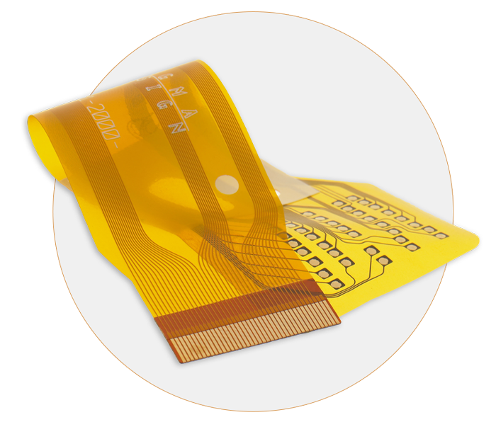
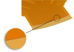
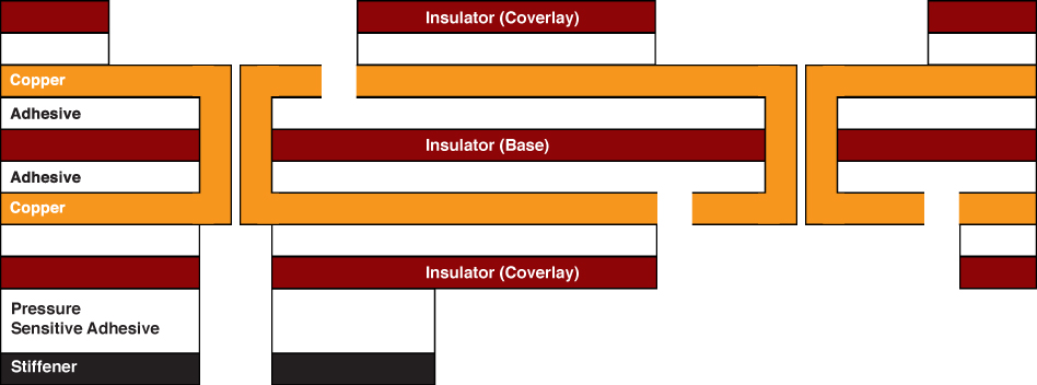
A dual access flex circuit is a single sided flex circuit that is manufactured so that the conductive material can be accessed from both sides of the circuit. Flexible Circuit is a front runner in this technology utilizing specialized lasers and processing to skive open the polyimide layer of the base material to allow for dual access to the single copper layer.


Flexible Circuit Technologies, a premier global supplier in design and production of
Flexible Circuits, Rigid Flex, Flexible Heaters, Flat Flex Cables, Membrane Switches, Plastic Moldings, Assemblies, Product Module Builds to Complete Product Box Builds
For more in depth information on Flex Printed Circuits, click on the links below:
As a connective device, the primary benefits of flexible circuits compared to traditional cabling and rigid boards include:
- Reduced wiring errors
- Elimination of mechanical connectors
- Unparalleled design flexibility
- Higher circuit density
- More robust operating temperature range
- Stronger signal quality
- Improved reliability and impedance control
- Size and weight reduction
There are many benefits to Flexible Printed Circuits including:
Assembly Error Reduction – With accurate designs and automated production, flex circuits eliminate human errors once involved in hand-built wire harnesses. With the exception of production-induced errors, circuits are ONLY routed to those points called for by the accurate design plan.
Decreased Assembly Time and Costs – Flex circuits require less manual labor during assembly and reduce production errors. Flex circuits have an intrinsic ability to integrate form, fit and function. Flex circuits eliminate the high cost of routing, wrapping and soldering wires. Complete interconnection systems are installed or replaced, rather than individual hard PC boards. As a result, wiring errors are eliminated and hence manufacturing costs are reduced. Whether it is a low volume production with a complex circuit or high volume production with a simple circuit, assembly time and costs are decreased.
Design Freedom – Unlike rigid boards, flex circuits are not restricted to two dimensions. Because they are as flexible as wires or ribbon cables, flex circuit design options are endless. At Flexible Circuit, we pride ourselves on taking on the most complex of design challenges. Flex circuits can be designed to meet highly complex and unimaginable configurations while being able to operate in the most hostile environments. Flex circuit designs could entail any of the following:
- Highly complex configurations
- Withstand hostile operating environments
- Single- Double- combinations
- Complex interconnections
- Shielding
- Rigid/flex capabilities
- Surface mounted devices
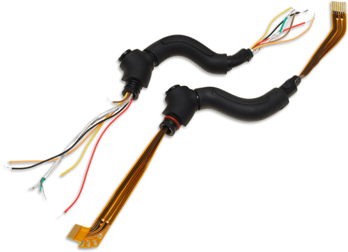
Wire harness conversion to flex reduces wiring errors from hand made connections and decreases assembly time
Flexibility during Installation – Flexible Circuits allow a third dimension to work with because they can interconnect between two or more planes during execution. As a result, they solve space and weight problems unmatched by rigid boards. Flex circuits can be manipulated many times during installation and execution without electronic failure.
High Density Applications – Flexible circuits allow for minutely narrow lines giving way to high density device population. Denser device populations and lighter conductors can be designed into a product, freeing space for additional product features.
Improved Airflow – Because of their streamlined design, flex circuits allow for the flow of cooling air through an electronic application.
Increased Heat Dissipation – Due to the larger surface-to-volume ratio and compact design of flexible circuits, a shorter thermal path is allowed. Further, the thinner design of flex circuits allows for heat dissipation from both sides of the circuit.
Increased System Reliability – In the past, most circuit failures occurred at an interconnection point. Flex circuits can be designed so that interconnections are reduced, which in turn, increases the reliability of a circuit.
Point-to-Point Wire Replacement – Depending on the number of point-to-point connections in a circuit design, at Flexible Circuit, we guarantee that we can design and build a single flex circuit that can eliminate many (if not all) of those interconnections. At Flexible Circuit, “We Go Where Others Will Not.”
Reliability and Durability – A flexible circuit can move and flex up to 500 million times without a failure, in designs that have moving parts. The exceptional thermal stability of polyimide also allows the circuit to withstand applications with extreme heat. The thermal stability of polyimide provides a better base for surface mounting than hard boards. Because the compliant base film places less stress on soldered joints, a thermal mismatch is less likely to occur.
Repeatable Routings – Our circuits are made from precise replicas of artwork for superior manufacturing consistency. The etched circuits replace the solder and hand wiring connections of the rigid board, completely eliminating wiring errors.
Simplified Circuit Geometry – Flexible Circuit Technologies places surface mount electronics directly onto the circuit which results in streamlining the overall design. Intricate patterns that were nearly impossible to achieve with rigid boards are made easily in flex circuits.
Package Size and Weight Reduction – Multiple systems in rigid boards create more weight and utilize more space. Flex circuits contain the thinnest dielectric substrates available. Thinness allows for a more streamlined design, eliminating the need for bulky rigid boards. The elasticity and flexibility allow package size reduction. In addition to package size reduction, package weight reduction is another benefit. With the ever increasing demands of the electronics industries, weight reduction keeps flex circuits very competitive.
Prior to designing a circuit, there are two fundamental structural applications that must be understood and dictate conductor selection:
Static Application – An application where flexible circuits are flexed only to install the circuit and fit it into its application (also known as flex-to-fit or flex-to-install). A static application will typically be made using the less expensive Electro Deposited (ED) copper.
Dynamic Flexing Applications – A situation where the flexible circuit itself is dynamically (repeatedly) flexed during the actual use of the final product. Common examples include flip-type cell phones, laptops, printer heads and robotic arms. A dynamic application will require the use of Rolled Annealed (RA) copper.
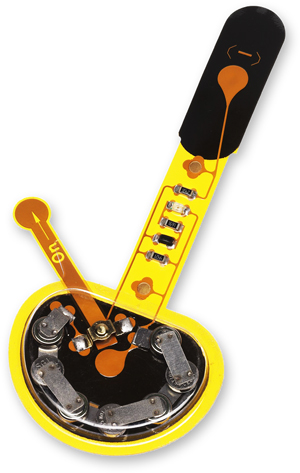
The benefits of flexible circuits are realized in most applications requiring high volume flexing and/or a high degree of accuracy. Some common applications include:
- Air bag systems
- Automotive engine controls
- Antilock brakes
- Avionics
- Bar code equipment
- Battery packs
- Calculators
- Cameras
- Cell phones
- Heart monitors and pacemakers
- Fuel pumps
- Hearing aids
- Printers
- Motion systems
- GPS systems
- Satellites
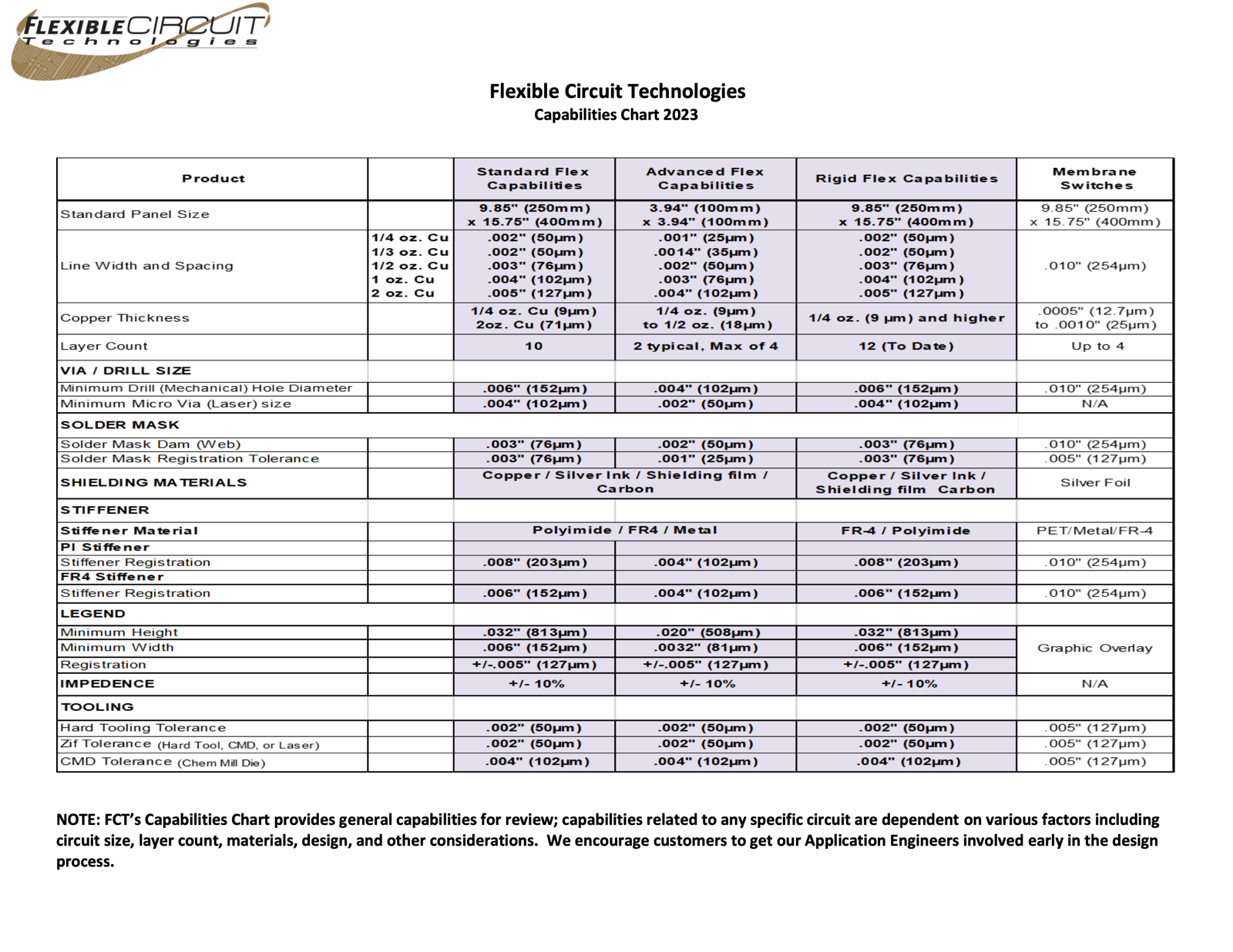

Conductors – Copper is the most widely used conductor and comes in various thicknesses to meet each customer’s requirements. Conductor options include:
- Rolled annealed (RA) copper
- Electro deposited (ED) copper
- Aluminum
- Carbon
- Silver ink
- Inconel®
- Constantan
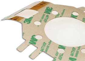
Adhesives – Adhesive selection depends on customer needs and conductor thickness. Common adhesives include:
- Epoxy
- Acrylic
- Pressure Sensitive Adhesives (PSAs)
- Adhesiveless (base material)
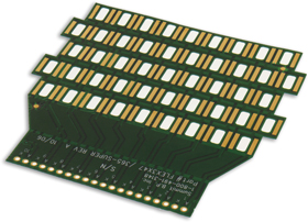
Insulators – Flexible substrate (base) and coverlay materials are available in a variety of thicknesses and from several manufacturers. Common insulators include:
- Polyimide
- Polyester, Polyethylene Naphthalate (PEN), and Polyethylene Terephthalate
(PET) - Solder mask
- Flexible solder mask
- Photo image-able coverlay (PIC)
- Screen printed dielectric
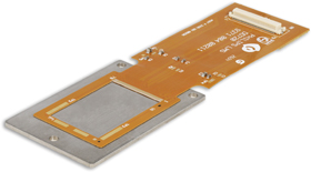
Finishes – The final finish depends on each customer’s assembly requirements and the application of the finished product. Common finishes include:
- Solder (Tin, Lead or RoHS compliant)
- Tin
- Immersion nickel/gold
- Hard nickel/gold
- Wire bondable gold
- Organic: entek or Organic Solderability Preservative (OSP)
- Silver
- Carbon
As the flex circuit market continues to expand, there have been many advances in technology including:
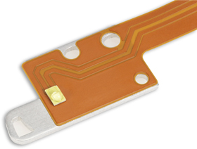
Heat Sinks – Heat sinks can be laminated to flex circuits to dissipate heat away from sensitive components such as LEDs.
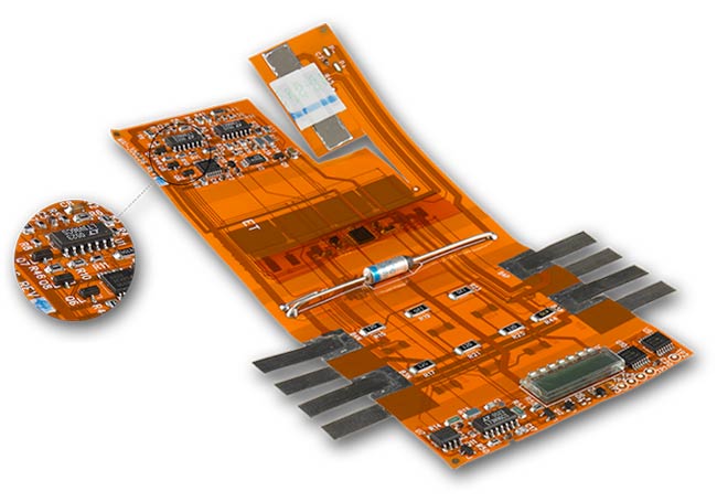
Component Assembly –We offer through hole and surface mount capabilities, as well as in circuit testing, conformal coating, and electrostatic protective packaging.
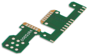
InControlled Impedance – With increasing signal switching speeds, engineers need to understand and control the impedance of traces. With short signal transition times and high clock rates of modern digital circuitry, traces need to be considered transmission lines instead of simple interconnections. With today’s higher speed requirements, controlled impedance traces are designed to minimize electrical reflections and ensure an error free transition between the track and interconnections. If perfectly optimized, controlled impedance allows control of the physical dimensions and material of the cable. Controlled impedance signal transmission requires flexible circuit materials to be uniform in both thickness and electrical properties. At Flexible Circuit Technologies, we have extensive experience in designing and manufacturing flex circuits with controlled impedance.
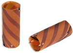
Crimp Pins – Crimp Pins are mechanically attached a circuit to allow for soldered connections.
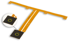
Graphic Overlays – Graphic Overlays can be placed over flexible circuits, rigid boards or membrane switches. The overlays provide the user interface with the underlying circuit and typically are used in conjunction with LEDs, LCD displays or dome switches mounted on thie circuits. The overlays are made from polycarbonate, polyester or acrylic materials.
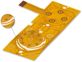
Laser Skived Slots and Holes – Historically, X-acto knives or razor blades were utilized to cut intricate areas of a flex circuit, the successful yield of which depended on the skill of the operator. FCT has dramatically improved this process by utilizing a top-of-the-line laser beam with extremely precise depth control to accurately cut the underlying substrate of a flex circuit. Precise laser beams can skive circuit openings with the utmost precision.
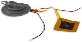
Overmolding – Overmolding is the process by which FCT embeds electronics versus simply placing electronics on the circuit. As electronic devices and required interconnections become more compact, embedding electronic circuitry within the cable assembly is a cost effective alternative to on-board electronics. Most often referred to as smart cables or dongles, these embedded devices can solve many packaging challenges.
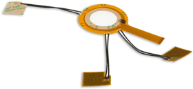
Pressure Sensitive Adhesives (PSAs) – PSAs with a release liner are used in applications where a portion(s) of the circuit needs to be secured to a specific location within the final product. During assembly, the release liner is peeled away and the exposed adhesive allows the assembler to press the circuit into place and keep it there.

Sculptured Flex Circuits – Sculptured flex circuits are special in that the copper conductors vary in depth and thickness in different places. The copper is thin at the most flexible part of the circuit and thick at the interconnection point. Sculptured flex circuits allow for bare metal connections (like a plug in) and remain strong at the solder joint formation. Sculptured fingers provide a more reliable alternative to mechanically fastened crimp pins.
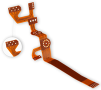
Stiffeners – Stiffeners are applied to flex circuits where additional support is needed such as areas of component assembly or underneath exposed traces that will be plugged in for connection. Common stiffeners are FR4 and polyimide.
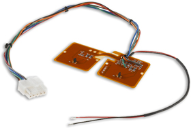
Wire Assembly – In certain applications a combination of flex or rigid circuit with traditional wire may be a more economical design that still meets the needs of the customer’s subassembly. At Flexible Circuit Technologies, we have the capabilities to design, source, manufacture and assemble the entire subassembly incorporating the circuit, wiring and components. This level of capabilities and commitment is what differentiates us from other flex circuit suppliers. It is also why our motto is “We Go Where Others Will Not”.
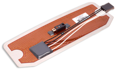
Flexible Heaters – Flexible heaters are thin, bendable heating elements, shaped to fit your unique heating equipment needs.

Hot Bar Solder – Hot bar solder connection is a way to eliminate a connector set between the hardboard and the flex circuit. This connection provides an efficient, durable and less expensive alternative to a standard connector set.



In summary, if you have flexible circuit design or flexible printed circuit board needs, we can help.