

Excellent for Confined and Changing Environments
Flat Flex Cables (FFC) are lightweight, low-profile, small-outline interconnect solutions engineered for high-density cabling applications where space, weight, and flexibility are critical. Also commonly referred to as Flexible Flat Cables, these cables consist of multiple flat conductors laminated between thin layers of insulating film, creating a ribbon-like structure that excels in dynamic and compact environments.


Key Characteristics and Design Advantages
- Repeated Dynamic Flexing: Designed for millions of flex cycles, they maintain electrical integrity under continuous bending, folding, or twisting, surpassing traditional round wire harnesses in high-movement applications.
- Exceptional Foldability and Stress Distribution: They can be folded into nearly any shape while evenly distributing mechanical stress across all conductors, reducing the risk of breakage or signal degradation.
- Low Profile and Space Efficiency: Occupying up to 50% less space than equivalent round cables, they hug surfaces and fit into tight or unused areas, enabling higher packaging density.
- Lightweight Construction: Significant weight savings compared to traditional cabling, which is valuable in portable, automotive, and aerospace-adjacent designs.
- Improved Heat Dissipation: The flat design offers greater surface area relative to volume, allowing better thermal management.
- EMI/RFI Benefits: Parallel conductor geometry often provides better electromagnetic interference suppression and eliminates wire-coupling issues common in round cables.
Benefits
A unique flat flexible circuit with many benefits:
- High Flex Life – Flat flex circuits are designed to flex and move throughout their life cycle. By virtue of their design, they will out-flex, or out-live, conventional wiring.
- Superior Heat Dissipation – Due to the larger surface-to-volume ratio and compact design of flat flex circuits compared to traditional round wire, a shorter thermal path is allowed.
- Light Weight – Compared to traditional round cables, flat flex circuits are extremely thin, making them considerably lighter.
- Low Profile – Especially when compared to traditional cable, flat flex circuits’ thin design can help resolve some of the most complex design challenges.
- Durability – Particularly, in designs that have moving parts, the flat flex circuit can move and flex up to 5 million times without a failure.
- Point-to-Point Wire Replacement – Depending on the number of point-to-point connections in a circuit design, flat flex circuits are an easy solution when connecting various components within an application.
- Foldable – Flat flexible circuit cabling can be folded many times over, enabling easier routing, particularly where space is limited.
- Multiple Termination Options – Flat flex circuits can be attached through a hot bar soldering process, through hole soldering, or a variety of different connectors.


Applications
Before getting into design options, there are two fundamental structural applications that must be understood about flat flex circuits:
Board to Board Connector – Depending on the number of point-to-point connections in a circuit design, flat flex circuits are an easy solution when connecting various components within an application.
Dynamic Flex Applications – When a flex circuit is dynamically flexed over and over within any given application, this is a high flex application. Common applications include: printer heads, copiers, and plotters.
Materials
Conductors
Copper is the most widely used conductor and it is typically flat, allowing extended flex life. Copper conductor options include:
- Bare copper
- Tin plated copper
Adhesives
Adhesive selection depends on customer needs and conductor thickness. Common adhesives include:
- Pressure Sensitive Adhesives (PSA)
- Acrylic
Insulators
Flexible substrate (base) and cover lay materials are available in a variety of thicknesses. Common insulators include:
- Polyester
- Polyethylene Naphthalate (PEN)
- Polyethylene Terephthalate (PET)
Finishes
The final finish depends on each customer’s assembly requirements and the application of the finished product. Common finishes include:
- Tin
Shielding
A protective shielding layer can be applied if required. Common shielding materials include:
- Conductive silver ink
- Aluminum or copper tape

Supplemental Information
The following chart provides a sample of the our manufacturing capabilities.
| Product | Standard Flex Capabilities | Advanced Flex Capabilities | Rigid Flex Capabilities | Printed Electronics | |
|---|---|---|---|---|---|
| Standard Panel Size | 9.85" (250mm) x 15.75" (400mm) | 3.94" (100mm) x 3.94" (100mm) | 9.85" (250mm) x 15.75" (400mm) | 9.85" (250mm) x 15.75" (400mm) |
|
| Line Width and Spacing | 1/4 oz. Cu 1/3 oz. Cu 1/2 oz. Cu 1 oz. Cu 2 oz. Cu | .002" (50µm) .002" (50µm) .003" (76µm) .004" (102µm) .005" (127µm) | .001" (25µm) .0014" (35µm) .002" (50µm) .003" (76µm) .004" (102µm) | .002" (50µm) .002" (50µm) .003" (76µm) .004" (102µm) .005" (127µm) | .010" (254µm) |
| Copper Thickness | 1/4 oz. Cu (9µm) 2oz. Cu (71µm) | 1/4 oz. (9µm) to 1/2 oz. (18µm) | 1/4 oz. (9 µm) and higher | .0005" (12.7µm) to .0010" (25µm) |
|
| Layer Count | 10 | 2 typical, Max of 4 | 12 (To Date) | Up to 4 | |
| VIA / DRILL SIZE | |||||
| Minimum Drill (Mechanical) Hole Diameter | .006" (152µm) | .004" (102µm) | .006" (152µm) | .010" (254µm) | |
| Minimum Micro Via (Laser) size | .004" (102µm) | .002" (50µm) | .004" (102µm) | N/A | |
| SOLDER MASK | |||||
| Solder Mask Dam (Web) | .003" (76µm) | .002" (50µm) | .003" (76µm) | .010" (254µm) | |
| Solder Mask Registration Tolerance | .003" (76µm) | .001" (25µm) | .003" (76µm) | .005" (127µm) | |
| SHIELDING MATERIALS | Copper / Silver Ink / Shielding film / Carbon | Copper / Silver Ink / Shielding film Carbon | Silver Foil | ||
| STIFFENER | |||||
| Stiffener Material | Polyimide / FR4 / Metal | FR-4 / Polyimide | PET/Metal/FR-4 | ||
| PI Stiffener | |||||
| Stiffener Registration | .008" (203µm) | .004" (102µm) | .008" (203µm) | .010" (254µm) | |
| FR4 Stiffener | |||||
| Stiffener Registration | .006" (152µm) | .004" (102µm) | .006" (152µm) | .010" (254µm) | |
| LEGEND | |||||
| Minimum Height | .032" (813µm) | .020" (508µm) | .032" (813µm) | Graphic Overlay | |
| Minimum Width | .006" (152µm) | .0032" (81µm) | .006" (152µm) | ||
| Registration | +/-.005" (127µm) | +/-.005" (127µm) | +/-.005" (127µm) | ||
| IMPEDENCE | +/- 10% | +/- 10% | +/- 10% | N/A | |
| TOOLING | |||||
| Hard Tooling Tolerance | .002" (50µm) | .002" (50µm) | .002" (50µm) | .005" (127µm) | |
| Zif Tolerance (Hard Tool, CMD, or Laser) | .002" (50µm) | .002" (50µm) | .002" (50µm) | .005" (127µm) | |
| CMD Tolerance (Chem Mill Die) | .004" (102µm) | .004" (102µm) | .004" (102µm) | .005" (127µm) | |
NOTE: FCT's capabilities Chart provides general capabilities for review; capabilities related to any specific circuit are dependent on various factors including circuit size, layer count, materials, design, and other considerations. We encourage customers to get our Application Engineers involved early in the design process.
As the flex circuit market continues to expand, there have been many advances in technology including:
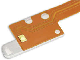
Heat Sinks – Heat sinks can be laminated to flex circuits to dissipate heat away from sensitive components such as LEDs.
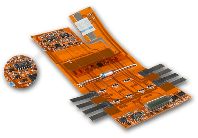
Component Assembly –We offer through hole and surface mount capabilities, as well as in circuit testing, conformal coating, and electrostatic protective packaging.
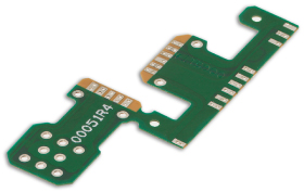
InControlled Impedance – With increasing signal switching speeds, engineers need to understand and control the impedance of traces. With short signal transition times and high clock rates of modern digital circuitry, traces need to be considered transmission lines instead of simple interconnections. With today’s higher speed requirements, controlled impedance traces are designed to minimize electrical reflections and ensure an error free transition between the track and interconnections. If perfectly optimized, controlled impedance allows control of the physical dimensions and material of the cable. Controlled impedance signal transmission requires flexible circuit materials to be uniform in both thickness and electrical properties. At Flexible Circuit Technologies, we have extensive experience in designing and manufacturing flex circuits with controlled impedance.
Crimp Pins – Crimp Pins are mechanically attached a circuit to allow for soldered connections.
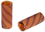
Graphic Overlays – Graphic Overlays can be placed over flexible circuits, rigid boards or membrane switches. The overlays provide the user interface with the underlying circuit and typically are used in conjunction with LEDs, LCD displays or dome switches mounted on thie circuits. The overlays are made from polycarbonate, polyester or acrylic materials.
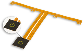
Laser Skived Slots and Holes – Historically, X-acto knives or razor blades were utilized to cut intricate areas of a flex circuit, the successful yield of which depended on the skill of the operator. FCT has dramatically improved this process by utilizing a top-of-the-line laser beam with extremely precise depth control to accurately cut the underlying substrate of a flex circuit. Precise laser beams can skive circuit openings with the utmost precision.
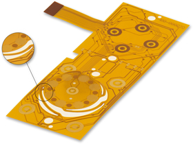
Overmolding – Overmolding is the process by which FCT embeds electronics versus simply placing electronics on the circuit. As electronic devices and required interconnections become more compact, embedding electronic circuitry within the cable assembly is a cost effective alternative to on-board electronics. Most often referred to as smart cables or dongles, these embedded devices can solve many packaging challenges.
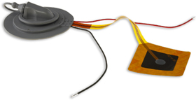
Pressure Sensitive Adhesives (PSAs) – PSAs with a release liner are used in applications where a portion(s) of the circuit needs to be secured to a specific location within the final product. During assembly, the release liner is peeled away and the exposed adhesive allows the assembler to press the circuit into place and keep it there.
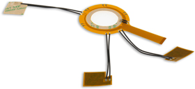
Sculptured Flex Circuits – Sculptured flex circuits are special in that the copper conductors vary in depth and thickness in different places. The copper is thin at the most flexible part of the circuit and thick at the interconnection point. Sculptured flex circuits allow for bare metal connections (like a plug in) and remain strong at the solder joint formation. Sculptured fingers provide a more reliable alternative to mechanically fastened crimp pins.

Stiffeners – Stiffeners are applied to flex circuits where additional support is needed such as areas of component assembly or underneath exposed traces that will be plugged in for connection. Common stiffeners are FR4 and polyimide.
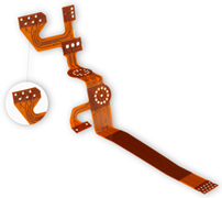
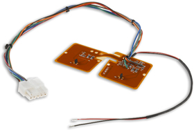
Wire Assembly – In certain applications a combination of flex or rigid circuit with traditional wire may be a more economical design that still meets the needs of the customer’s subassembly. At Flexible Circuit Technologies, we have the capabilities to design, source, manufacture and assemble the entire subassembly incorporating the circuit, wiring and components. This level of capabilities and commitment is what differentiates us from other flex circuit suppliers. It is also why our motto is “We Go Where Others Will Not”.
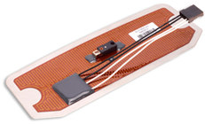
Flexible Heaters – Flexible heaters are thin, bendable heating elements, shaped to fit your unique heating equipment needs.
Hot Bar Solder – Hot bar solder connection is a way to eliminate a connector set between the hardboard and the flex circuit. This connection provides an efficient, durable and less expensive alternative to a standard connector set.

Dual Access – Laser skiving of single sided circuits ensures smooth, low profile, dual access.

