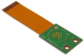
Rigid Flex
Rigid flex circuits have been used in the military and aerospace industries for more than 40 years. In rigid flex circuit boards, layers of flexible and rigid materials are used to create both rigid and flexible areas in a single package.
Rigid flex circuits combine the best of both rigid boards and flexible circuits integrated together into one circuit.
Rigid outer layers are connected to inner flexible layers using copper plated vias. Rigid flex circuits provide higher component density and better quality control. Designs are rigid where extra support for SMT components is needed, and is and flexible in areas that need to bend and flex to fit into tight spaces.


Flexible Circuit Technologies, a premier global supplier in design and production of
Flexible Circuits, Rigid Flex, Flexible Heaters, Flat Flex Cables, Membrane Switches, Plastic Moldings, Assemblies, Product Module Builds to Complete Product Box Builds
For more in depth information on Rigid Flex, click on the links below:
There are many high level benefits to Rigid Flex circuits including:
Connection Reliability – Connecting rigid layers with flexible cables is the foundation for combination rigid flex circuits. Rigid flex constructions eliminate the need for board-to-board connectors or wiring harnesses to link rigid boards together.
Lower Part Count – Compared to a traditional rigid board, rigid flex circuits require fewer parts and interconnections by eliminating wire harnesses and board-to board connectors.
Flexible Design Options –
At Flexible Circuit Technologies, we pride ourselves on guiding customers on the most complex of design challenges to provide the most reliable and cost-effective designs. Rigid flex circuits can be designed to meet highly complex and unimaginable configurations by utilizing both rigid and flexible substrates. Rigid flex circuit designs can incorporate any of the following:
- Highly complex configurations
- Controlled Impedance
- High layer count
- Reduced interconnections
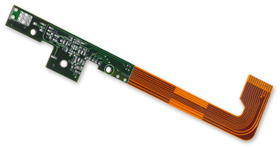
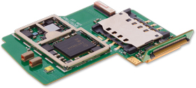
High Density Applications – By eliminating interconnecting hardware, rigid flex can free up space allowing for higher connection density. More often than not, the rigid areas of a rigid flex circuit are utilized for high density SMT device population. The flexible regions connecting the rigid areas allow the circuit to be formed into a 3-dimensional shape, with multiple interconnected rigid areas on different planes.
Package Size and Weight Reduction – Due to the ultra-thin nature of flexible circuit materials and the ability to create very narrow circuit traces, much higher connection density is possible along with a significant reduction in overall system weight. The inherent lower mass of rigid flex makes this interconnect system ideal in high shock and vibration applications.
There are two main functional applications for rigid flex. These are static (flex-to-install) and dynamic (continuous flexing over the life of the product). The design and construction of the rigid flex will be dependent on whether the application is static or dynamic.

Static Application – An application where the flex circuit is only required to flex during installation in order to fit it into its application (also known as flex-to-install).
Dynamic Flexing Applications – An application where the flexible area is dynamically flexed during normal operation. This can range from a few hundred cycles up to over 1 million cycles.
Advances in rigid circuit board technology has broadened the applications in electronic products from computer, communication, and consumer electronics, to automotive, medical, and military electronics. Increasing demand for more powerful and smaller products drives the need for multiple layers to accommodate denser, finer line width and spacing and smaller hole sizes.
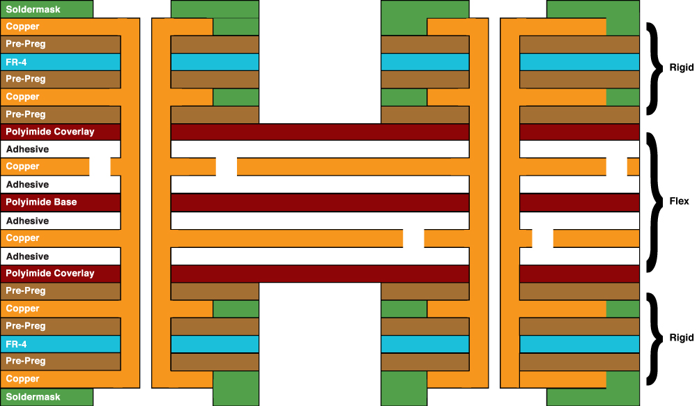
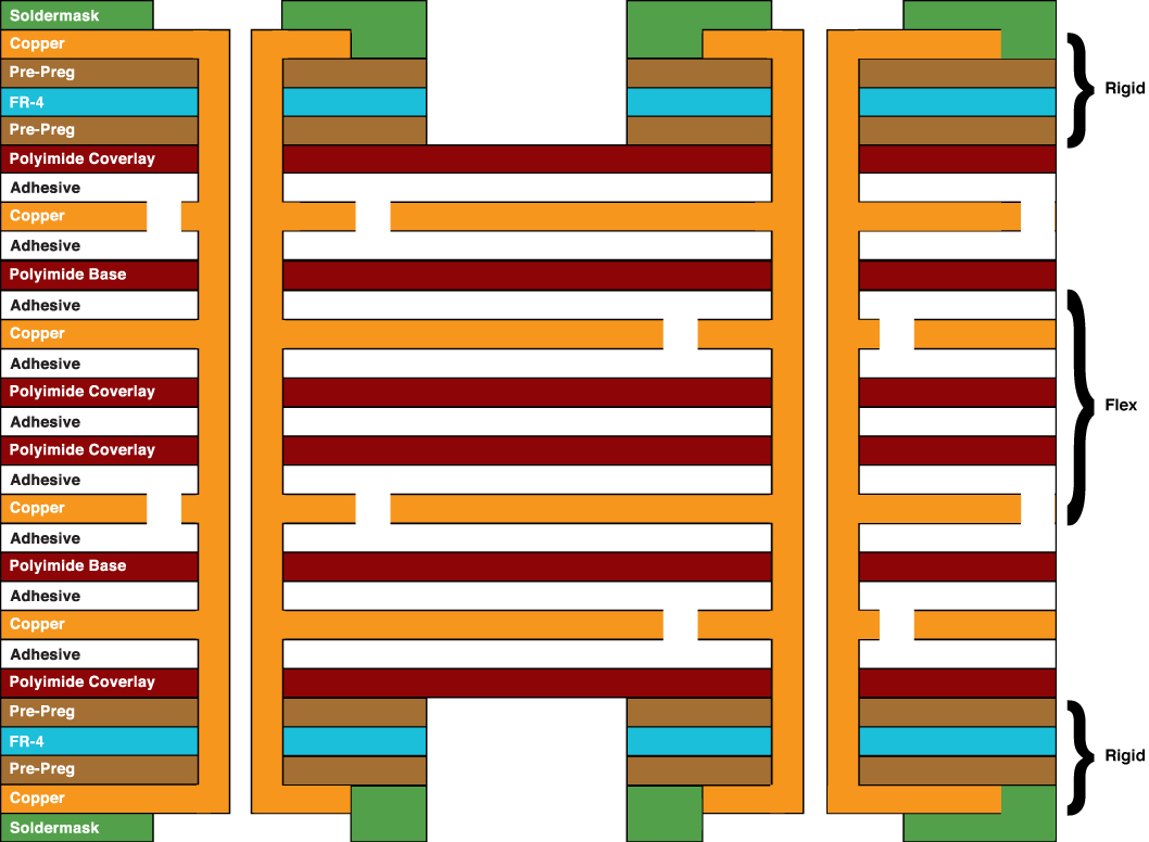
Conductors – Copper is the most widely used conductor for building flex and rigid flex. Copper is available in various thicknesses to meet customer’s requirements for current carrying capacity and voltage drop. Copper thickness is typically specified in ounces/square foot. The most common thicknesses are 1/3 oz (.0005”/12um), ½ oz (.0007”/15um), 1 oz (.0014”/35um, and 2 oz (.0028”/70um) Conductor options include:
- Rolled annealed (RA) copper
- Hyper Annealed copper (HA)
- Electro deposited (ED) copper
Adhesives – Adhesive selection depends on customer needs and conductor thickness. Common adhesives include:
- Modified epoxy film
- Modified acrylic film
- Epoxy/glass pre-preg
- Pressure Sensitive Adhesive (PSA)
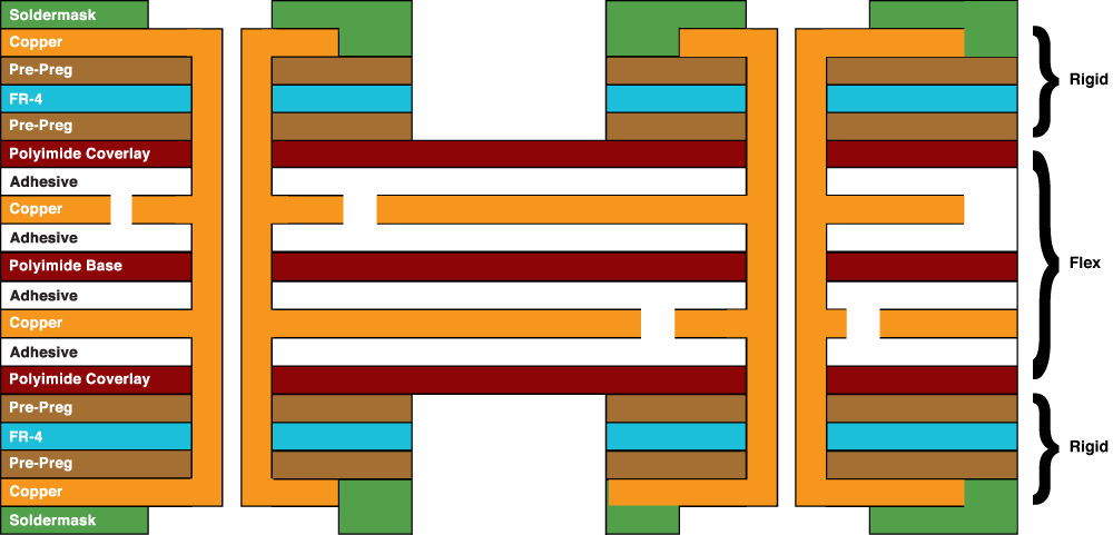
Insulators/Dielectrics – Flexible substrate (base) and cover lay materials are available in a variety of thicknesses from .001”/25um to .005”/125um. Common dielectrics include:
- Polyimide film
- FR-4 (rigid epoxy/glass)
- Solder mask
- Photo image-able cover lay (PIC)
Finishes – The final finish depends on each customer’s assembly requirements and the application of the finished product. Common finishes include:
- ENIG (Electroless Nickel Immersion Gold)
- ENEPIG (Electroless Nickel Electroless Palladium Immersion Gold)
- Solder (Tin/Lead RoHS compliant)
- Hard nickel/gold
- Wire bondable gold
- Tin
- Organic Solderability Preservative (OSP)
- Silver
As the Rigid flex circuit market continues to expand, there have been many advances in technology including:

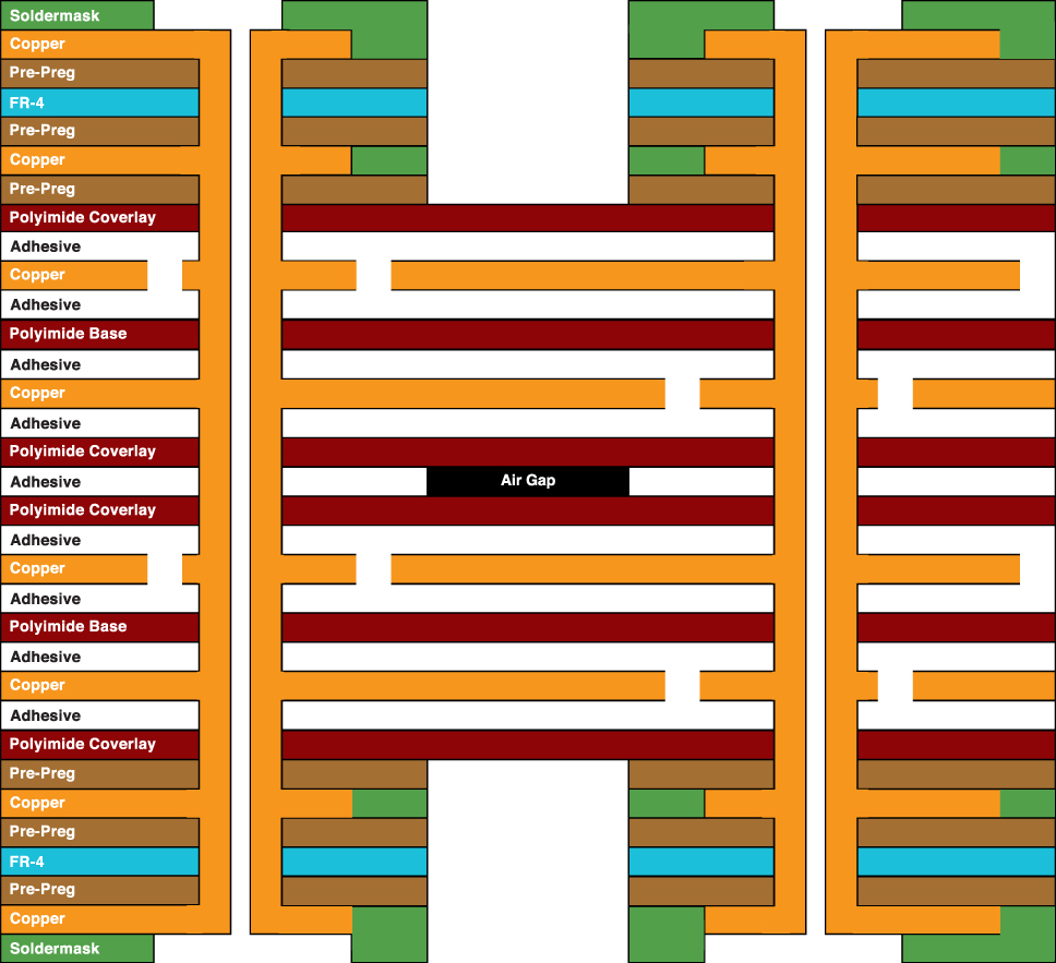
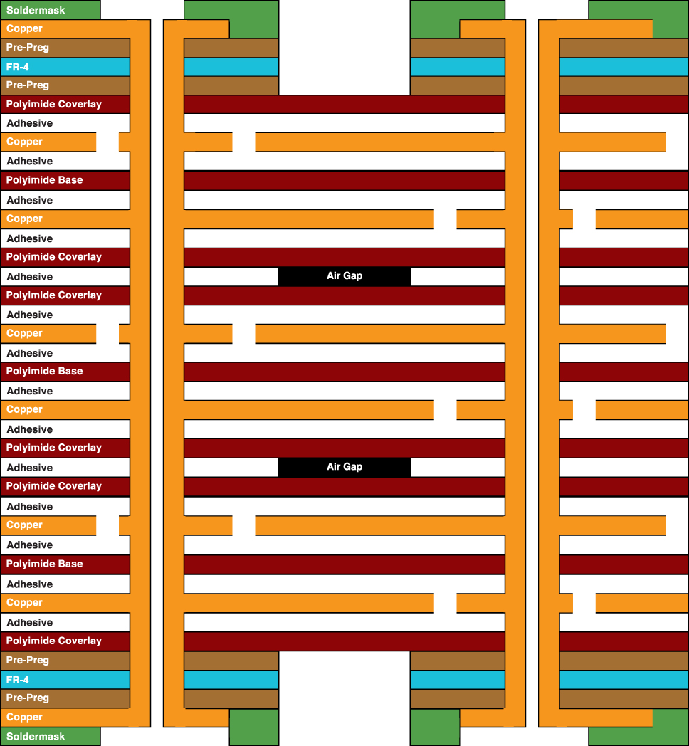
Air Gap – Through the process of selective bonding, increased flexibility is achieved by “unbonding” layers so they are allowed to flex freely. At Flexible Circuit Technologies, we are fully capable to support air gap technology applications allowing your designs more flexibility.
 Component Assembly – Flexible Circuit Technologies offers through hole and surface mount capabilities, as well as in circuit testing, conformal coating and electrostatic protective packaging.
Controlled Impedance – With increasing signal switching speeds, engineers need to understand and control the impedance of sensitive signal lines. With short signal transition times and high clock rates of modern digital circuitry, traces need to be considered transmission lines rather than simple interconnections. With today’s higher speed requirements, controlled impedance traces are designed to minimize electrical reflections and ensure an error free transition between the trace and terminations. Controlled impedance requires tight control of the physical dimensions of the etched copper traces (width and thickness), and also the thickness of the dielectric materials. Controlled impedance signal transmission requires flexible circuit materials to be uniform in both thickness and electrical properties.
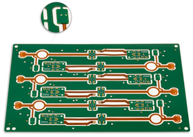
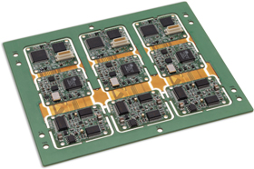
Panelization – Multiple circuits are partially routed with break-away tabs to allow them to remain in the panel for component assembly during the “pick & place” and wave soldering processes. Once the panel of rigid flex circuit boards are assembled, simply clip them out by cutting or v-scoring the break-away tabs and they are ready for assembly into your final product.
Pressure Sensitive Adhesives (PSAs)– In addition to widespread use for bonding mechanical stiffeners to flex and rigid flex, PSA with a release liner is also used in applications where portion of the circuit needs to be secured to a specific location within the final product. During assembly, the release liner is peeled away and the exposed adhesive allows the assembler to press the circuit into place and keep it there.
Shielding – Shielding is typically specified when an application requires controlled impedance, and/or limits in electromagnetic and/or electrostatic interference. Common shielding options are:
- Copper (solid or cross hatched)
- Shielding film (e.g. Tatsuta)
- Silver or carbon ink
In summary, if you have flexible circuit design or flexible printed circuit board needs, we can help.